2020. 3. 11. 09:58ㆍAnalog/Filters
출처 : https://www.electronics-tutorials.ws/filter/filter_5.html

Active Low Pass Filter
By combining a basic RC Low Pass Filter circuit with an operational amplifier we can create an Active Low Pass Filter circuit complete with amplification
In the RC Passive Filter tutorials, we saw how a basic first-order filter circuits, such as the low pass and the high pass filters can be made using just a single resistor in series with a non-polarized capacitor connected across a sinusoidal input signal.
We also noticed that the main disadvantage of passive filters is that the amplitude of the output signal is less than that of the input signal, ie, the gain is never greater than unity and that the load impedance affects the filters characteristics.
With passive filter circuits containing multiple stages, this loss in signal amplitude called “Attenuation” can become quiet severe. One way of restoring or controlling this loss of signal is by using amplification through the use of Active Filters.
As their name implies, Active Filters contain active components such as operational amplifiers, transistors or FET’s within their circuit design. They draw their power from an external power source and use it to boost or amplify the output signal.
Filter amplification can also be used to either shape or alter the frequency response of the filter circuit by producing a more selective output response, making the output bandwidth of the filter more narrower or even wider. Then the main difference between a “passive filter” and an “active filter” is amplification.
An active filter generally uses an operational amplifier (op-amp) within its design and in the Operational Amplifier tutorial we saw that an Op-amp has a high input impedance, a low output impedance and a voltage gain determined by the resistor network within its feedback loop.
Unlike a passive high pass filter which has in theory an infinite high frequency response, the maximum frequency response of an active filter is limited to the Gain/Bandwidth product (or open loop gain) of the operational amplifier being used. Still, active filters are generally much easier to design than passive filters, they produce good performance characteristics, very good accuracy with a steep roll-off and low noise when used with a good circuit design.
Active Low Pass Filter
The most common and easily understood active filter is the Active Low Pass Filter. Its principle of operation and frequency response is exactly the same as those for the previously seen passive filter, the only difference this time is that it uses an op-amp for amplification and gain control. The simplest form of a low pass active filter is to connect an inverting or non-inverting amplifier, the same as those discussed in the Op-amp tutorial, to the basic RC low pass filter circuit as shown.
First Order Low Pass Filter

This first-order low pass active filter, consists simply of a passive RC filter stage providing a low frequency path to the input of a non-inverting operational amplifier. The amplifier is configured as a voltage-follower (Buffer) giving it a DC gain of one, Av = +1 or unity gain as opposed to the previous passive RC filter which has a DC gain of less than unity.
The advantage of this configuration is that the op-amps high input impedance prevents excessive loading on the filters output while its low output impedance prevents the filters cut-off frequency point from being affected by changes in the impedance of the load.
While this configuration provides good stability to the filter, its main disadvantage is that it has no voltage gain above one. However, although the voltage gain is unity the power gain is very high as its output impedance is much lower than its input impedance. If a voltage gain greater than one is required we can use the following filter circuit.
Active Low Pass Filter with Amplification

The frequency response of the circuit will be the same as that for the passive RC filter, except that the amplitude of the output is increased by the pass band gain, AF of the amplifier. For a non-inverting amplifier circuit, the magnitude of the voltage gain for the filter is given as a function of the feedback resistor ( R2 ) divided by its corresponding input resistor ( R1 ) value and is given as:

Therefore, the gain of an active low pass filter as a function of frequency will be:
Gain of a first-order low pass filter

- Where:
- AF = the pass band gain of the filter, (1 + R2/R1)
- ƒ = the frequency of the input signal in Hertz, (Hz)
- ƒc = the cut-off frequency in Hertz, (Hz)
Thus, the operation of a low pass active filter can be verified from the frequency gain equation above as:
- 1. At very low frequencies, ƒ < ƒc

- 2. At the cut-off frequency, ƒ = ƒc
- 3. At very high frequencies, ƒ > ƒc

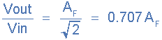
Thus, the Active Low Pass Filter has a constant gain AF from 0Hz to the high frequency cut-off point, ƒC. At ƒC the gain is 0.707AF, and after ƒC it decreases at a constant rate as the frequency increases. That is, when the frequency is increased tenfold (one decade), the voltage gain is divided by 10.
In other words, the gain decreases 20dB (= 20*log(10)) each time the frequency is increased by 10. When dealing with filter circuits the magnitude of the pass band gain of the circuit is generally expressed in decibels or dB as a function of the voltage gain, and this is defined as:
Magnitude of Voltage Gain in (dB)

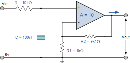
Active Low Pass Filter Example No1
Design a non-inverting active low pass filter circuit that has a gain of ten at low frequencies, a high frequency cut-off or corner frequency of 159Hz and an input impedance of 10KΩ.
The voltage gain of a non-inverting operational amplifier is given as:

Assume a value for resistor R1 of 1kΩ rearranging the formula above gives a value for R2 of:

So for a voltage gain of 10, R1 = 1kΩ and R2 = 9kΩ. However, a 9kΩ resistor does not exist so the next preferred value of 9k1Ω is used instead. Converting this voltage gain to an equivalent decibel dB value gives:

The cut-off or corner frequency (ƒc) is given as being 159Hz with an input impedance of 10kΩ. This cut-off frequency can be found by using the formula:
| where ƒc = 159Hz and R = 10kΩ. |
By rearranging the above standard formula we can find the value of the filter capacitor C as:

Thus the final low pass filter circuit along with its frequency response is given below as:
Low Pass Filter Circuit
Frequency Response Curve

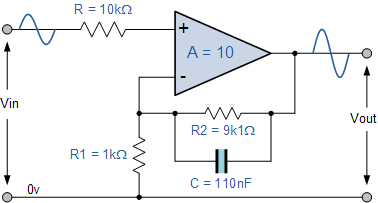
If the external impedance connected to the input of the filter circuit changes, this impedance change would also affect the corner frequency of the filter (components connected together in series or parallel). One way of avoiding any external influence is to place the capacitor in parallel with the feedback resistor R2 effectively removing it from the input but still maintaining the filters characteristics.
However, the value of the capacitor will change slightly from being 100nF to 110nF to take account of the 9k1Ω resistor, but the formula used to calculate the cut-off corner frequency is the same as that used for the RC passive low pass filter.

An example of the new Active Low Pass Filter circuit is given as.
Simplified non-inverting amplifier filter circuit
Equivalent inverting amplifier filter circuit

Applications of Active Low Pass Filters are in audio amplifiers, equalizers or speaker systems to direct the lower frequency bass signals to the larger bass speakers or to reduce any high frequency noise or “hiss” type distortion. When used like this in audio applications the active low pass filter is sometimes called a “Bass Boost” filter.
Second-order Low Pass Active Filter
As with the passive filter, a first-order low-pass active filter can be converted into a second-order low pass filter simply by using an additional RC network in the input path. The frequency response of the second-order low pass filter is identical to that of the first-order type except that the stop band roll-off will be twice the first-order filters at 40dB/decade (12dB/octave). Therefore, the design steps required of the second-order active low pass filter are the same.
Second-order Active Low Pass Filter Circuit

When cascading together filter circuits to form higher-order filters, the overall gain of the filter is equal to the product of each stage. For example, the gain of one stage may be 10 and the gain of the second stage may be 32 and the gain of a third stage may be 100. Then the overall gain will be 32,000, (10 x 32 x 100) as shown below.
Cascading Voltage Gain


Second-order (two-pole) active filters are important because higher-order filters can be designed using them. By cascading together first and second-order filters, filters with an order value, either odd or even up to any value can be constructed. In the next tutorial about filters, we will see that Active High Pass Filters, can be constructed by reversing the positions of the resistor and capacitor in the circuit.
'Analog > Filters' 카테고리의 다른 글
| Active Band Pass Filter (0) | 2020.03.11 |
|---|---|
| Active High Pass Filter (0) | 2020.03.11 |
| Passive Band Pass Filter (0) | 2020.03.11 |
| Passive High Pass Filter (0) | 2020.03.11 |
| Passive Low Pass Filter (0) | 2020.03.11 |